Simplify Flange Design With COMPRESS
Flanges provide the primary means of connecting pressure vessels and heat exchangers to process piping. Because of the number of variables involved, designing a custom Appendix 2 flange can be a difficult task. Designing a pair of flanges introduces even more complications as does adding consideration of flange leakage. Even the seemingly simple task of specifying standard ASME B16.5/16.47 flanges involves considerations beyond the rating tables. For example, how do you take piping loads into account? It should come as no surprise that engineers have spent their entire careers looking into ways of dealing with flanged joints. Fortunately, COMPRESS provides intuitive tools to help with these tasks.


Designing Flange Pairs to Appendix 2-5(a)(2)
Designing Flange Pairs to Appendix 2-5(a)(2)
COMPRESS automatically considers mating flange bolt loads as required by ASME VIII-1, Appendix 2-5(a)(2). When would a designer run into this situation you might ask? Heat Exchanger designs are where this situation is most often encountered.
Tube side and shell side flanges share common bolting, may have different gasketing and are simultaneously subject to different pressures. The question is which side and condition governs the joint? Appendix 2-5(a)(2) addresses this situation directly. Bolt loads from gasket seating and operating conditions are determined for each flange and the controlling load is used for the design of both flanges.
COMPRESS can also determine Appendix 2 flange maximum allowable working pressures (MAWP). As there is no direct solution, COMPRESS iterates the pressures of the shell side and tube side until one of the allowable stresses is reached.
Obviously flange design (or analysis) is much more complicated when performed on a pair of mating flanges. In this case, the flanges have a common link, the bolting. The MAWP (or MAP) of a flange may be restricted so as not to overstress the bolts or to prevent one of flanges from being overstressed. There is some judgment required here as well. In certain cases the MAWP of one flange will be directly controlled by the maximum pressure of the mating flange. In other words, increasing the MAWP of one flange may reduce the MAWP of the mating flange.
External Flange Loadings (Piping Loads)
External Flange Loadings (Piping Loads)
Making sure all mechanical loadings are considered on the flange design is critical in ensuring a tight joint. Applied external loadings introduce yet another layer of complexity in flange design. COMPRESS automatically handles this in multiple ways:
Appendix 2 Flanges
If a body flanges are attached to a vertical cylinder or cone and Wind or Seismic has been specified, COMPRESS calculates the loading and applies it automatically. In addition, the weight supported by the flanges is taken into account. Alternatively, a User defined Moment/Radial Load may be specified.
When attaching flanges to a conical section without a knuckle or flare radius, the superposition of the discontinuity stresses is unknown. In this case, COMPRESS calculates the discontinuity stresses as if the cone were attached directly to the adjacent cylinder.
B16.5/16.47 Flanges
COMPRESS uses the rules from UG-44 to account for external loadings on B16.5/16.47 rated flanges. Essentially, an equivalent pressure is determined based on the moments from the applied external loads. These are commonly nozzle (piping) loads taken from the COMPRESS WRC-107/537 dialog which must accounted for on the flange as well.
PCC-1 Appendix O – Flange Assembly Rules
PCC-1 Appendix O – Flange Assembly Rules
COMPRESS provides the ability to assess bolted joints per ASME PCC-1 Appendix O. This procedure provides guidance on determining the appropriate assembly bolt torque\stress with due consideration for joint integrity.
Two approaches are available, the simple approach and the joint approach.
With the simple approach, an appropriate bolt stress is determined based on the target gasket stress. This is then converted to a target bolt torque.
With the joint approach, the following conditions are considered before arriving at a target bolt torque:

Appendix Y Flange Design
Appendix Y Flange Design
COMPRESS has the ability to design flanges that comply with ASME VIII-1, Appendix Y. The stress analysis for Appendix Y flanges differs from Appendix 2 flanges in that they have metal to metal contact outside the bolt circle. Gasket sealing is usually provided by a self energizing (soft) o-ring type gasket material for Appendix Y flanges.

Gasket Library Included
Gasket Library Included
COMPRESS comes with a convenient library of gaskets for users to choose from. Gasket suppliers listed include Flexitallic, Garlock, Lamons, and Teadit. Need a gasket from a supplier that isn’t on the list? Simply add the gasket to the library for future use.

Automatic Flange Design
Automatic Flange Design
COMPRESS provides a Flange Wizard to help automatically select flange dimensions and optimize flange designs. The Flange Wizard provides several options to guide the Wizard including maximum bolt count and minimum bolt diameter. From here users can choose to direct COMPRESS to adjust the gasket, make bolt hole clearance changes or maintain gasket position and bolt hole clearance.

UG-34 Bolted Covers
UG-34 Bolted Covers
Flat bolted covers designed per UG-34 are not independent components like cylinders or transitions. They are dependent on the attached flange with respect to bolt circle, gasketing, flange facing details and so forth. COMPRESS addresses this by allowing bolted covers to be designed in conjunction with Appendix 2 or ASME B16.5/B16.47 standard flanges. This sharing of information between flanges and bolt covers saves time and prevents mistakes.

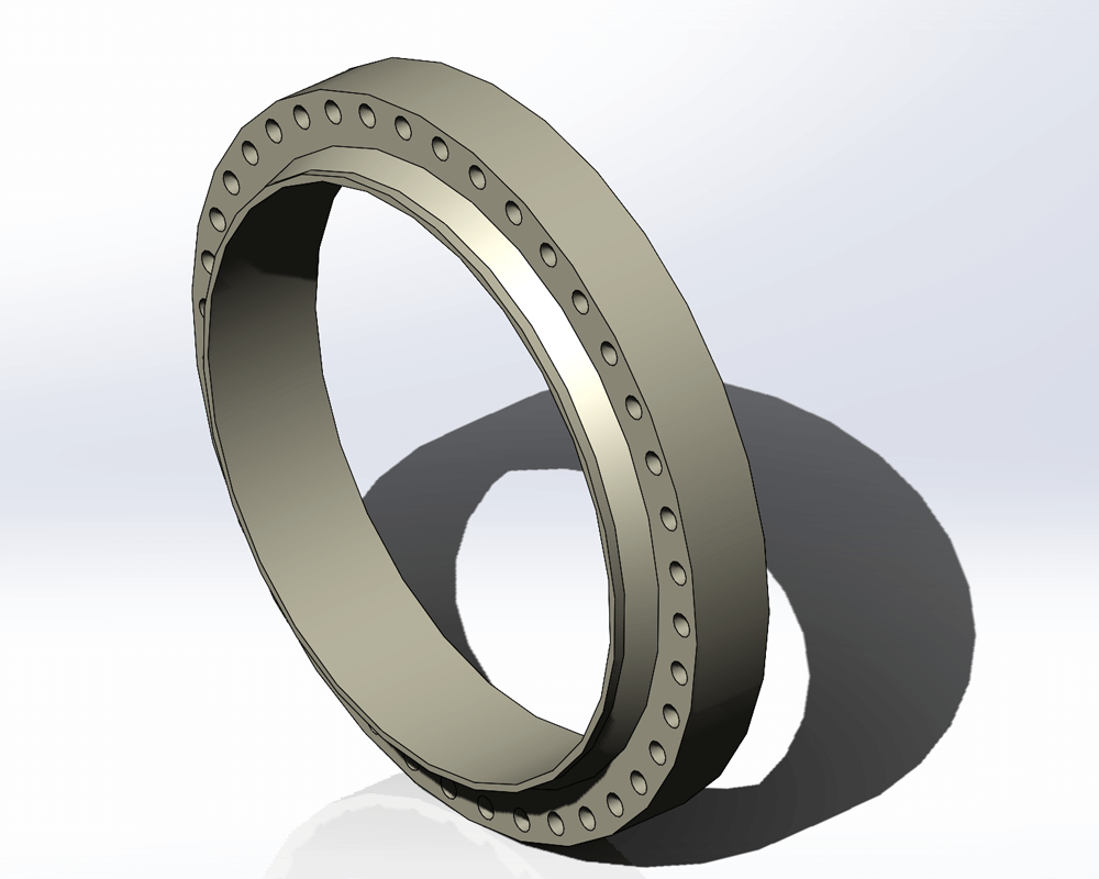
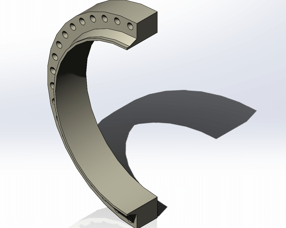
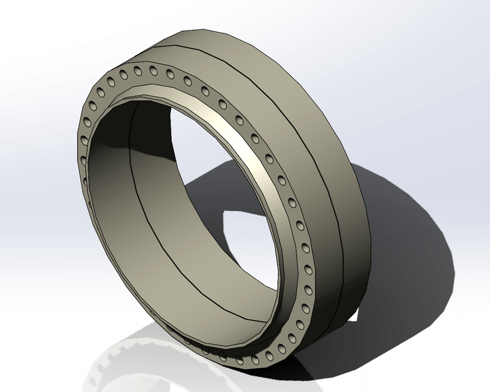
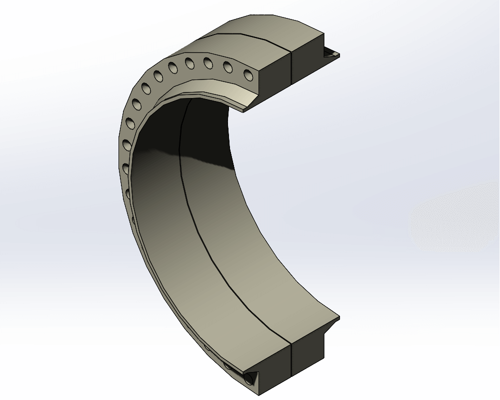
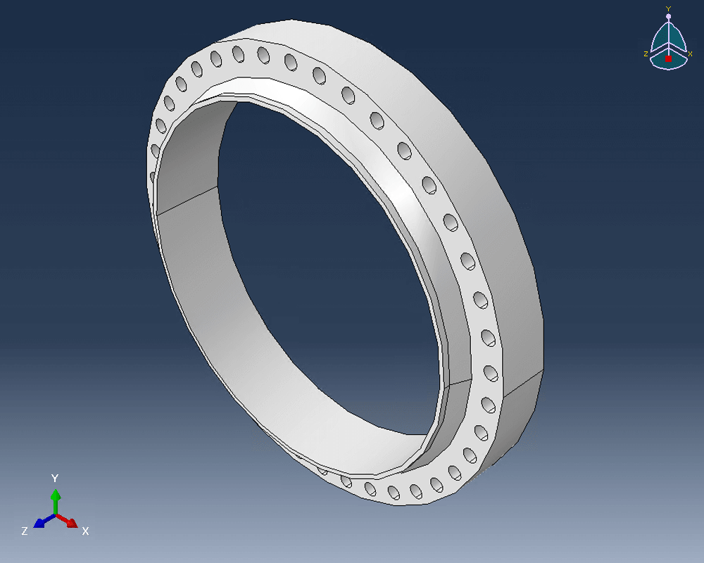
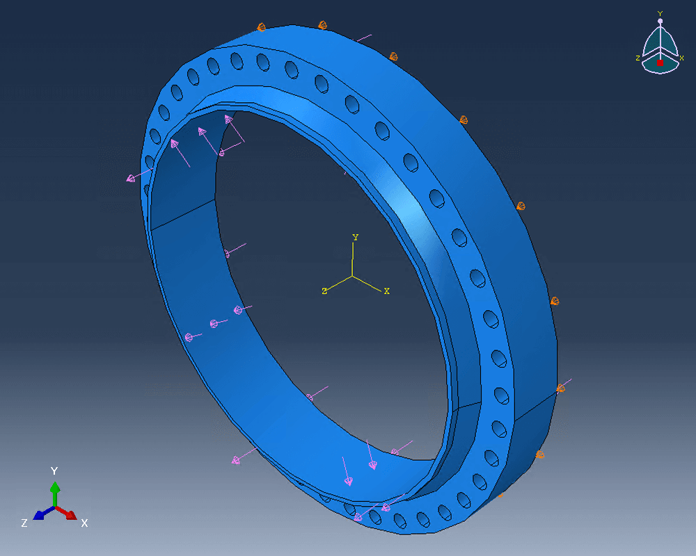
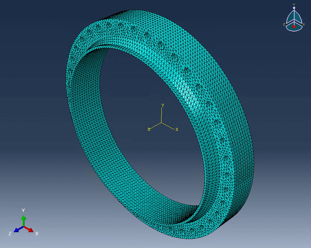
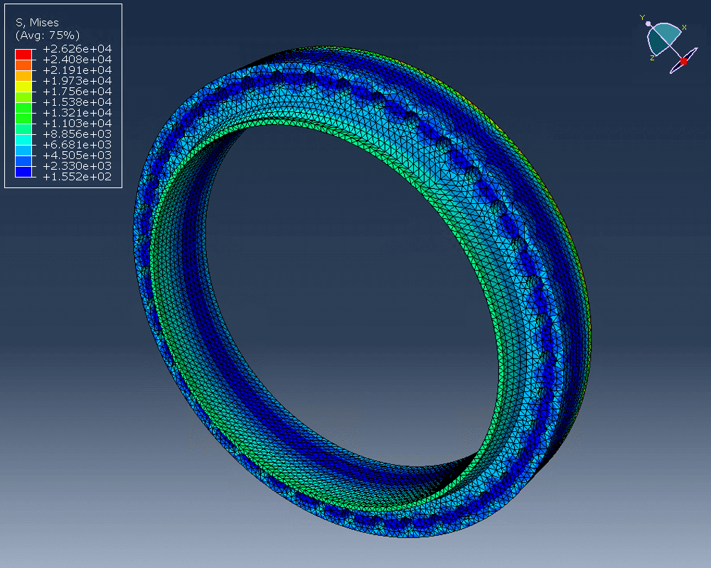
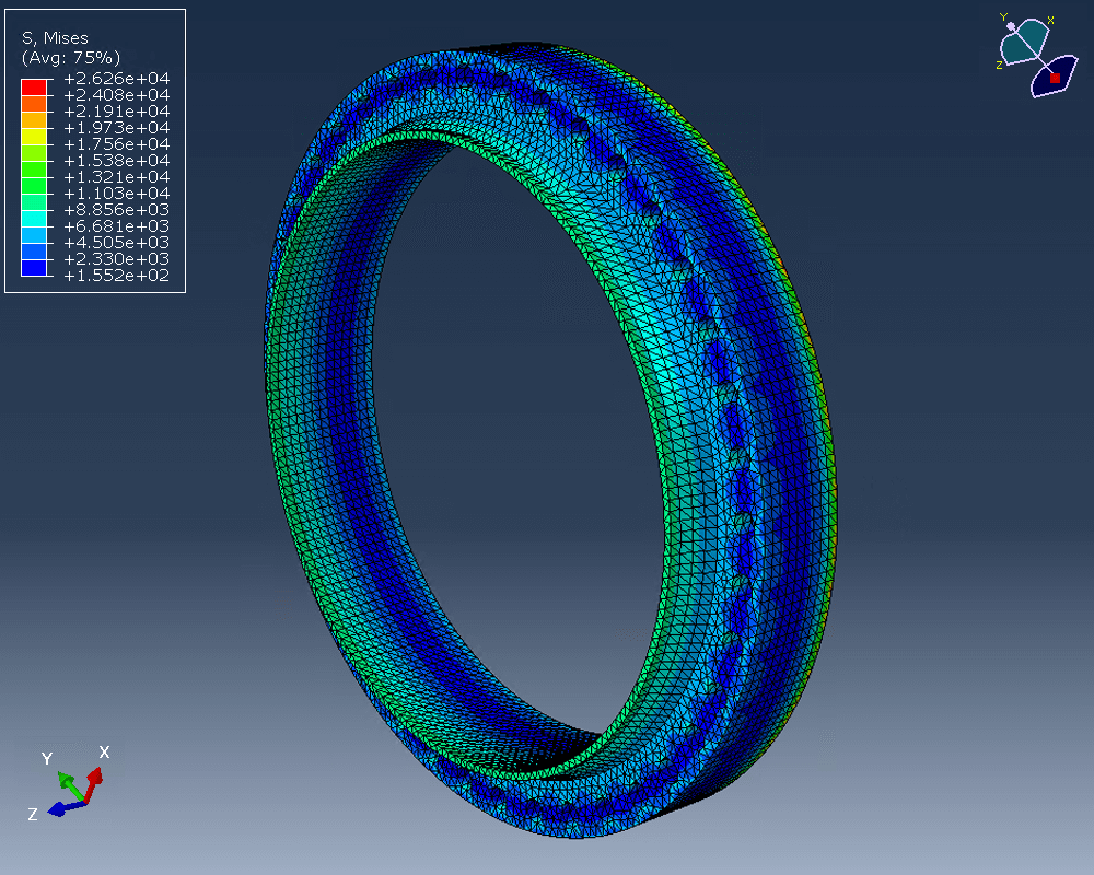
U-2(g) Flange Analysis
U-2(g) Flange Analysis
Do you need to perform special U-2(g) assessments on flanges? COMPRESS makes it easy to model and export solid model files to 3rd party FEA software such as ABAQUS. No need to worry about getting the flange hub dimensions right or the bolt circle correct. The built-in COMPRESS 3D solid model takes care of the geometry for you so you can focus on your Engineering analysis.
Increase Your Capabilities With COMPRESS
UG-28 rules for external pressure design and vacuum rating.


+1 (941) 927-2670 | sales@codeware.com